Baroxon® | Leading Boom Barrier Manufacturer

How Does an Automatic Parking Barrier System Work?
Release time:
2026-11-02
Introduction: More Than Just an Arm Going Up and Down
An automatic parking barrier system controls vehicle movement at the entrance and exit of an area. When a vehicle arrives, the system detects its presence, verifies access permission through methods such as RFID or ANPR/LPR, then sends a command to the barrier controller to drive the motor and raise the arm. After the vehicle has safely passed, the system lowers the arm again according to the configured control logic.
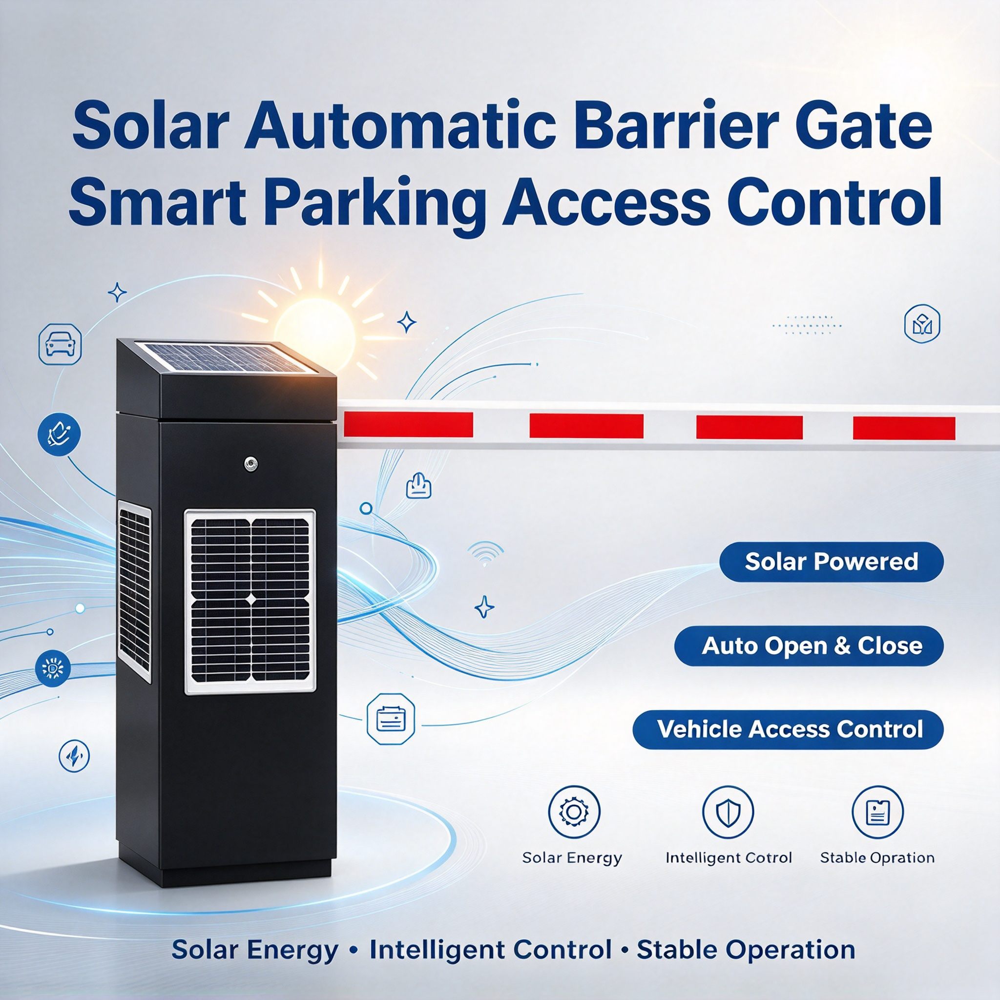
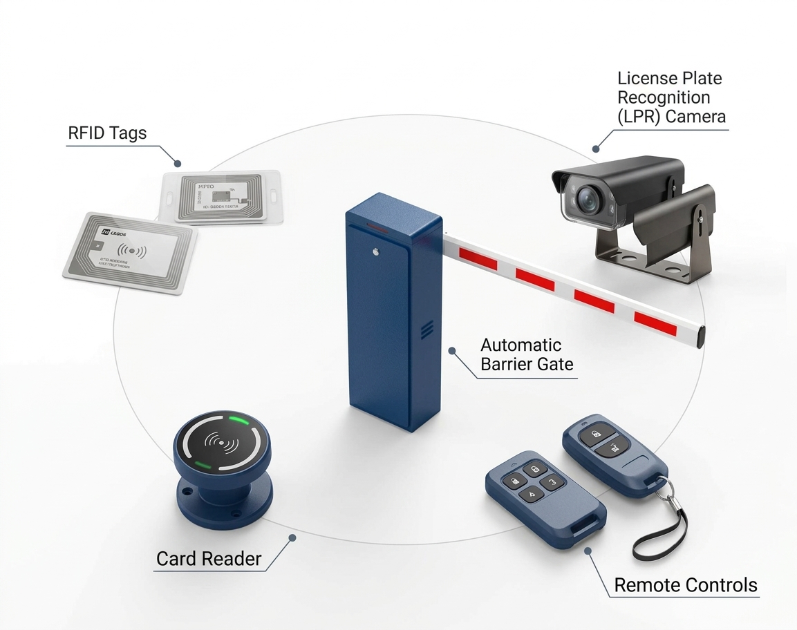
A boom barrier is therefore not a device that works on its own. It is usually part of an access control system that may include RFID/UHF readers, number plate recognition cameras, radar or inductive loop sensors, safety photocells, an electronic controller and parking management software. BAROXON provides a range of boom barriers, high-speed barrier gates, ALPR/LPR systems, automatic RFID boom barriers, radar sensors and accessories that can be evaluated according to project requirements.
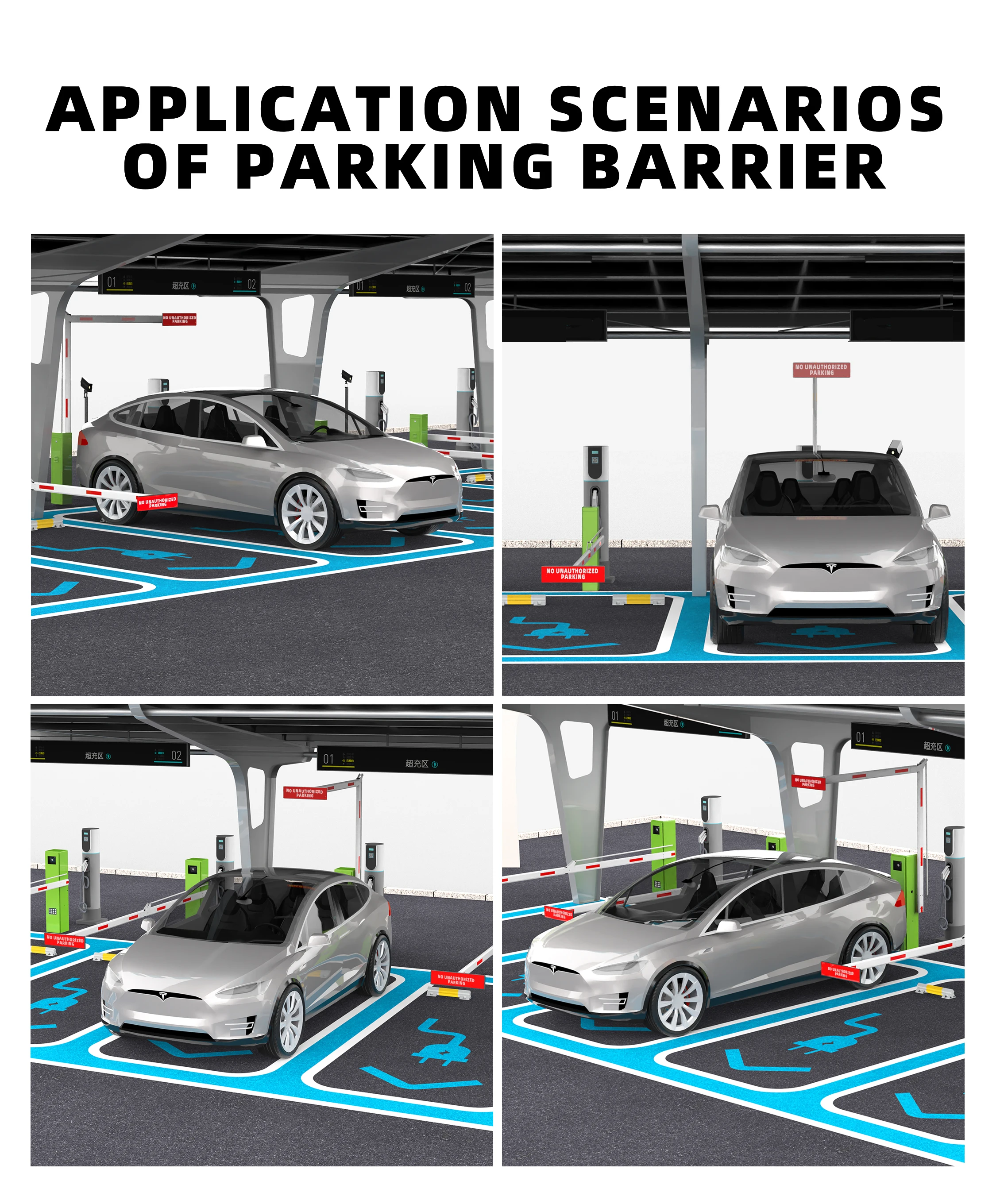
1. Key Components of an Automatic Parking Barrier System
Before understanding the operating sequence, it helps to know the components that usually work together in one vehicle control lane. The actual arrangement depends on the barrier model, the access verification method and the site design.
1.1 Barrier cabinet, arm and drive mechanism
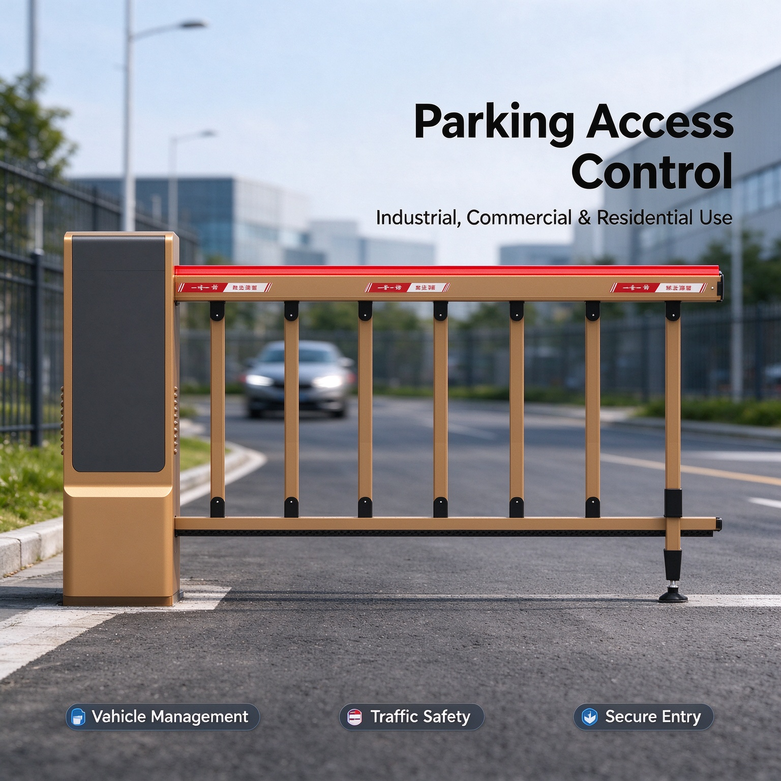
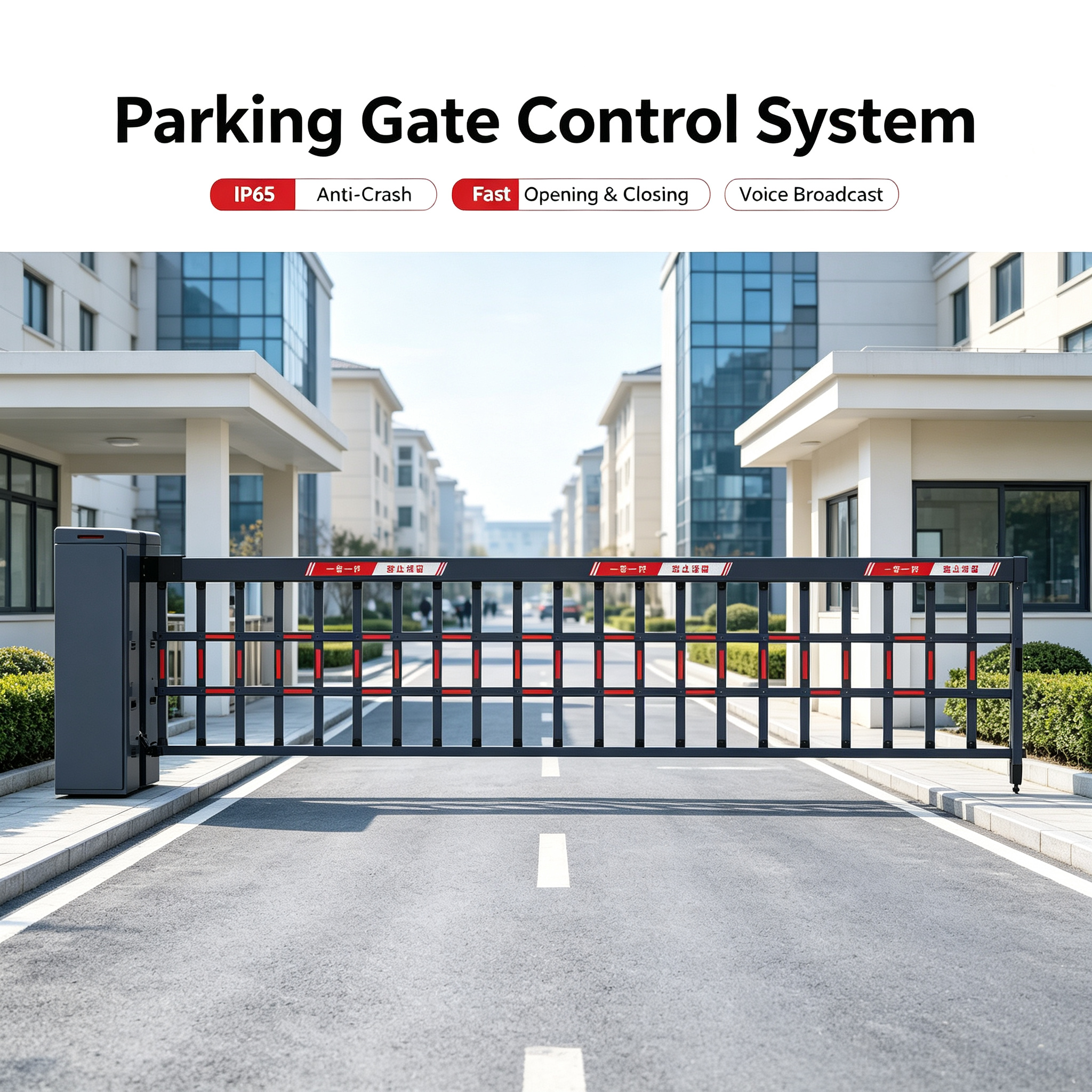
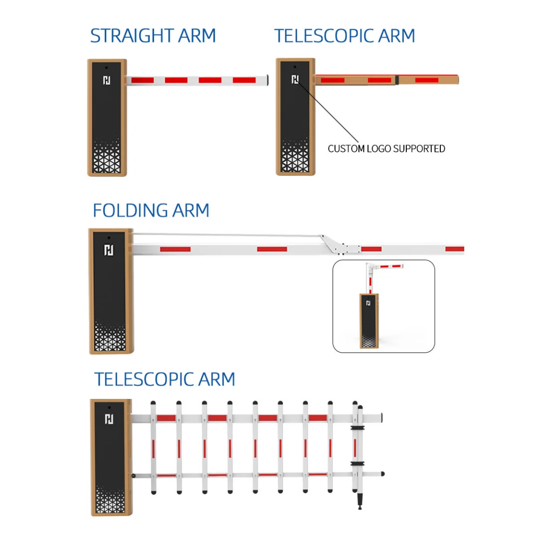
The barrier cabinet houses the drive mechanism and control components. The motor drives a gear or transmission system to raise and lower the barrier arm. Depending on the model, the arm can use a straight, folding or fence configuration. Arm length, weight and mounting method must be matched to the lane width and operating space.
1.2 Motor and electronic control board
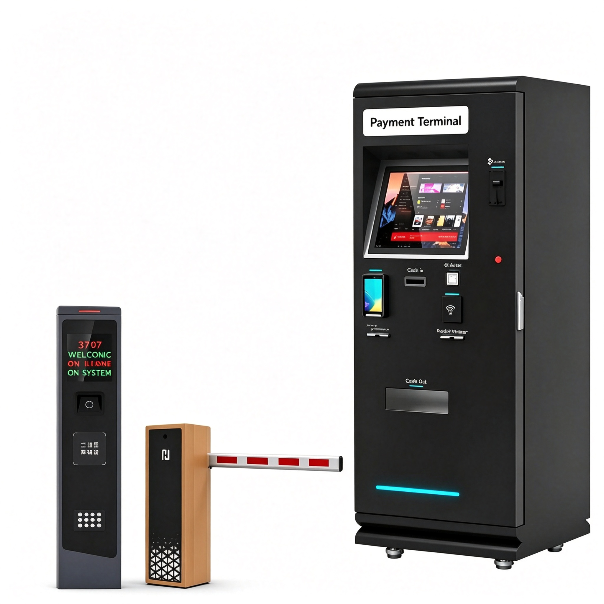
The motor produces mechanical movement, while the electronic control board receives open/close commands and controls the drive operation. BAROXON lists 24V DC brushless, AC and servo motor configurations on selected models. Depending on the model, the control board can also provide interfaces for access and detection devices.
1.3 Access verification devices
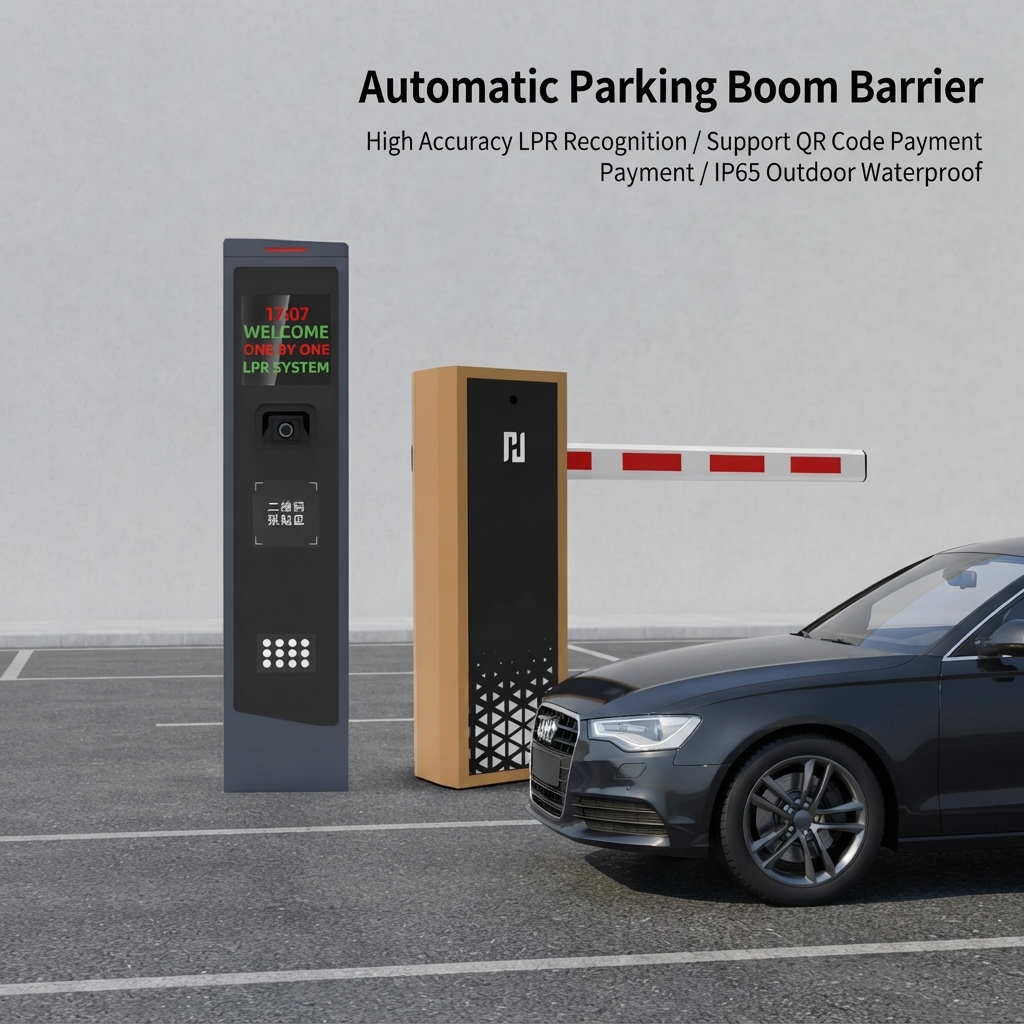
These devices determine whether a vehicle or user is allowed to enter. Common options include RFID card readers, long-range UHF readers, ANPR/LPR cameras, QR codes or remote controls. Not every project needs all of these methods; the choice depends on the operating process and existing systems.
1.4 Detection and safety sensors
Sensors detect the presence of a vehicle or an obstacle in the area where the arm moves. Depending on the lane design, the system may use radar, an inductive loop detector, a photocell or a combination of devices. The selected sensors should suit the vehicle position, weather conditions and site risk.
1.5 Parking management software
The software manages the list of allowed vehicles, access rules, entry and exit time records and other operating functions. In an integrated system, the software can communicate with LPR cameras, RFID readers, the barrier controller and payment or parking management systems, subject to interface compatibility.
2. How the System Works: Step-by-Step Operating Flow
In general, the operation of one automatic lane can be understood through six stages: the vehicle is detected, identity or eligibility is checked, access is approved, a command is sent to the controller, the arm opens, and the lane is confirmed clear before the arm closes. The actual sequence may differ according to the configuration.
Step 1: The vehicle arrives and is detected
When a car approaches the entry lane, radar or a presence sensor detects the vehicle. In certain configurations, an inductive loop detector installed below the road surface detects a change in the electromagnetic field when a vehicle is over the loop. This detection can be used to trigger the camera, access reader or the next control sequence.
Step 2: The system identifies the vehicle or user
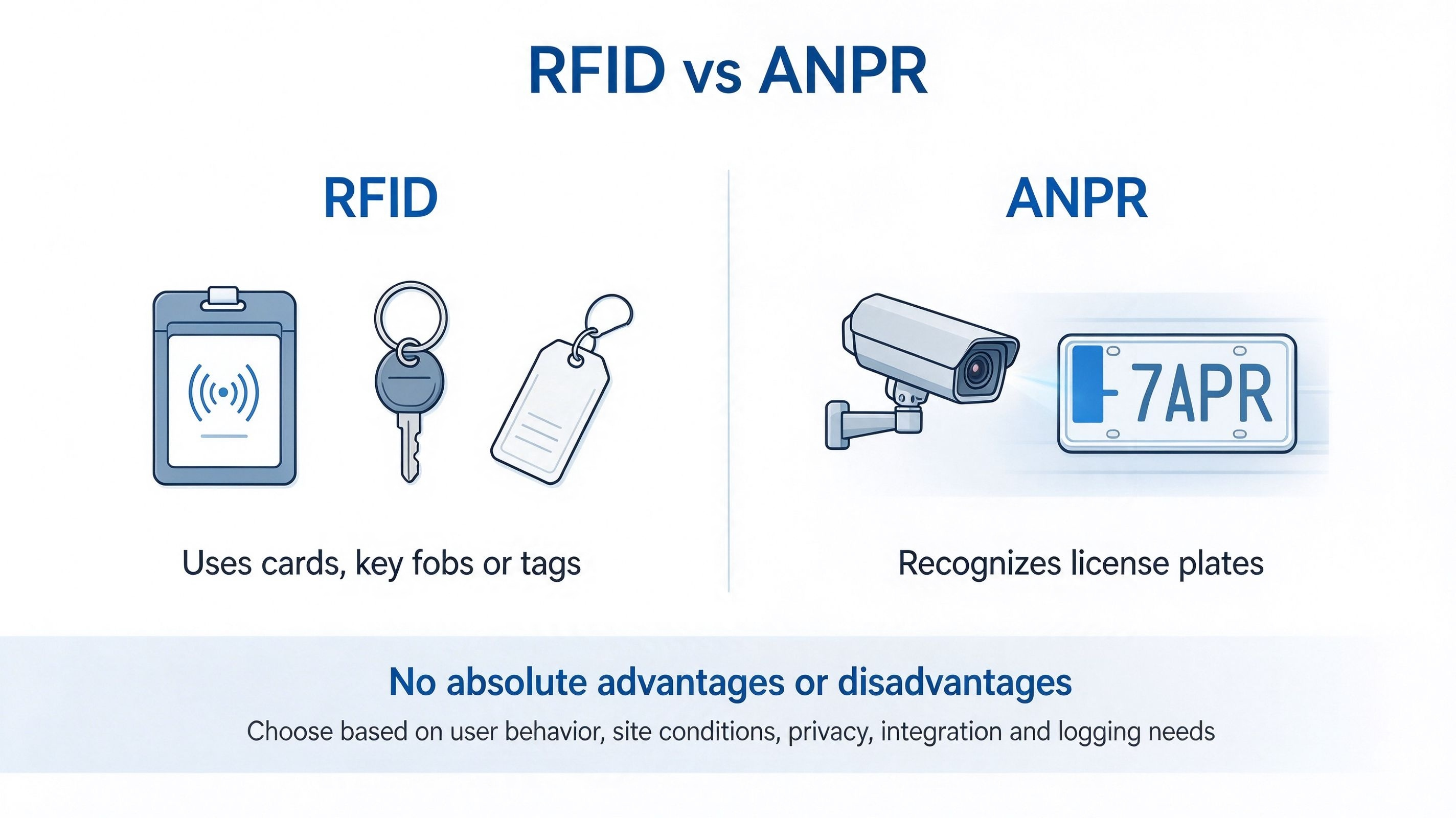
With RFID, the reader detects a registered card or tag. For UHF systems, the antenna reads the tag at a distance set by the reader, tag and installation conditions. With ANPR/LPR, the camera captures an image of the number plate and the software attempts to recognize the registration characters.
Step 3: Access eligibility is checked
Card, tag or number plate data is sent to the access controller or management software. The system compares the data with the allowed user list, subscription status, access period or other preset rules. If the information matches and access is allowed, the system generates a command to open the barrier. If not, the arm remains closed and follow-up action can be taken by a security guard or operator.
Step 4: The open command is sent to the barrier control board
After access is approved, the access system sends a signal to the barrier control board. Depending on the equipment, communication can use a dry contact relay, RS485, TCP/IP or another supported interface. The control board receives the command and activates the motor drive according to the model settings.
Step 5: The motor raises the barrier arm
The motor moves the drive mechanism to raise the arm to the open position. The speed and travel time depend on the model, arm length and type, control settings and installation conditions. The controller can use position limits or mechanism feedback to manage arm movement.
Step 6: The vehicle passes and sensors confirm the lane
While the vehicle moves under the arm, presence or safety sensors help determine whether the lane area is still occupied. The system should not lower the arm merely because a set time has elapsed if detection shows that a vehicle is still in the danger zone. This logic must be designed and tested according to the actual layout.
Step 7: The arm closes and the access record is updated
After the sensors confirm that the lane is clear and safety conditions are met, the controller instructs the motor to lower the arm. The management system can store the time, card identity or registration number, lane and access result. These records help operators review parking usage, handle complaints and investigate incidents.
3. How RFID, UHF and ANPR/LPR Differ
The access verification method determines how the system recognises a vehicle before the arm opens. These three approaches can be used separately or combined if the controller and software support the integration.
RFID or access card systems
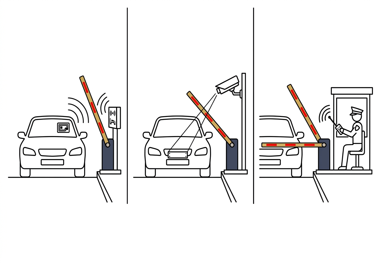
The user scans a card or uses a registered tag. The reader sends the identification data to the access controller, and the system then checks permission. This method is suitable for residents, employees or regular users who each have a card or tag.
Long-range UHF systems
A UHF reader can read a vehicle tag without the user needing to get out of the car or scan a card manually, depending on the reading distance and configuration. Performance is affected by the tag type, antenna position, mounting angle, vehicle speed and radio interference at the location.
ANPR/LPR systems
The camera captures an image of the registration number, the software reads the characters and the system checks the number against the access database. If the plate is recognized well and has permission, the system can send an open command to the barrier. Camera angle, lighting, plate condition, weather and vehicle speed all need attention.
4. How Sensors Make Operation Safer
Safety sensors play an important role because the barrier arm moves across the vehicle lane. The system needs to detect vehicles or obstacles in the relevant zone and prevent movement that could cause a collision. The actual features and response depend on the model, sensor type, wiring and control configuration.
Inductive loop detector
An inductive loop is installed below the road surface and is used to detect the presence of a vehicle in a specific zone. Depending on the system logic, it can help keep the arm open while a vehicle is in the detection area.
Radar sensor
Radar detects objects or vehicle movement without needing a loop cut into the road surface. The radar model and its mounting method determine the detection zone and the ability to detect direction or presence. On-site testing should ensure that detection is not triggered accidentally by traffic in an adjacent lane.
Photocell and obstacle detection
A photocell uses an infrared beam between a transmitter and receiver to detect an interruption in the beam path. Some barrier configurations also support obstacle detection and an auto-reverse or rebound function. Make sure the required function is actually available on the chosen model and is tested during commissioning.
5. How the Barrier Communicates with the Parking System
In an integrated system, the barrier needs to receive commands from other devices or software. Interfaces such as a dry contact relay, RS485 or TCP/IP can be used according to the model and project design. Before installation, the integrator should check the signal types, communication protocol, device addresses, power supply and command sequence.
For example, an LPR camera can send a recognition result to the parking software. After the registration number is approved, the access controller sends an open signal to the barrier control board. Sensors then report the lane status so the system can manage arm closure more safely. The actual integration should be tested end to end, not merely confirmed that each device can be powered on.
6. Example Flow at a Condominium Entrance
At a apartment complex entrance, residents may use a UHF tag on the vehicle or an RFID card, while visitors need to be registered by a security guard or through a visitor system. When a resident's vehicle approaches the lane, the reader detects the tag and checks permission. If approved, a command is sent to the barrier to open the arm.
While the vehicle passes the arm, sensors detect whether the lane is still occupied. After the vehicle leaves the safety zone, the barrier closes again and the entry record is stored. If the tag is not recognized or the system fails to verify access, the vehicle can be directed to the guardhouse for manual checking.
7. Example Flow at a Warehouse or Logistics Area
At warehouses and logistics centers, the lane may receive trucks, trailers and delivery vehicles throughout the day. The system can combine a UHF reader to identify vehicle tags, radar to detect presence or direction of movement, and a boom barrier to control passage. The management system can also record entry time, tag ID and delivery information if integration is provided.
For 24-hour operations, motor selection, duty cycle, cabinet protection, detection method and maintenance plan should be evaluated together. Do not choose maximum speed without considering arm length, vehicle weight, stopping distance and traffic conditions in the area.
8. What Happens If the Power or Network Fails?
If the power supply is interrupted, the electric motor may not be able to perform normal operations. Some models provide a manual release mechanism or a backup power option, but these features must be confirmed based on the model and configuration purchased. Operators should also have an emergency procedure for managing vehicle flow during an outage.
If the network or management software is unavailable, the system response depends on the control architecture. Some systems can process cards or commands locally, while others may depend on a server or network connection. Before operation, determine whether access should fail secure or whether an emergency release method approved by the site safety assessment is required.
9. Factors Affecting System Performance
Overall performance is not determined by the motor alone. It is affected by arm length and type, vehicle volume, verification method, sensor position, installation quality, power supply stability, software integration and maintenance. A weakness in one component can affect the entire entry and exit flow.
For Malaysia's hot, humid and heavy-rain environment, check the cabinet protection level, anti-corrosion finish, cable protection and drainage method. BAROXON lists several models with protection options such as IP54, IP65 or IP66; the actual level should be confirmed on the data sheet of the chosen model.
10. How to Choose the Right BAROXON Configuration
BAROXON offers several vehicle access control categories, including boom barriers and boom gates, high-speed barrier gates, automatic RFID boom barriers, ALPR/LPR car plate systems, radar sensors and barrier accessories. To determine a suitable combination, start by identifying the site type, lane width, vehicle volume, access method and required safety level.
| Site requirement | Configuration to evaluate |
|---|---|
| Condominium or gated community | Boom barrier + RFID/UHF or ANPR/LPR |
| Office and commercial center | Boom barrier + access card or integrated parking system |
| Lane with limited vertical space | Folding arm barrier |
| Warehouse and logistics area | Heavy-duty barrier + UHF + radar |
| Public parking lot with automatic management | High-speed barrier + ANPR/LPR + parking software |
Before ordering, prepare a site plan, entrance photos, lane width, vehicle types, estimated hourly traffic, preferred access method, integration requirements and environmental conditions. Ask for written confirmation of the motor model, arm length, speed, duty cycle, IP rating, communication interface, safety sensors and emergency operating method. You can explore BAROXON's barrier gate and parking access range before finalising the configuration.
Frequently Asked Questions
1. What is the main function of an automatic parking barrier system?
Its main function is to control vehicle entry and exit by verifying access, moving the barrier arm and managing the lane based on sensor information. An integrated system can also record transactions or vehicle movement.
2. Can a boom barrier work without RFID or ANPR?
Yes. A barrier can be controlled by a remote control, switch, guard button or another compatible access system. RFID and ANPR/LPR are optional verification methods, not a requirement for every installation.
3. What is the difference between RFID and ANPR/LPR?
RFID identifies a card or tag read by a reader, while ANPR/LPR uses a camera and software to read a vehicle's registration number. The choice depends on how users are registered, operating requirements and site conditions.
4. Why are sensors needed on a boom barrier?
Sensors help detect vehicles or obstacles in the area where the arm moves. They can help prevent the arm from lowering while a vehicle is still in a risky area. Sensor types and control logic must be selected and tested according to the site.
5. Can a BAROXON system be integrated with existing parking software?
Integration can be evaluated based on the interfaces and protocols supported by the model and the software. Check the dry contact relay, RS485, TCP/IP or other connections stated in the product documentation, then run an integration test before the system is used.
6. Can the system operate in the rain?
Models with a suitable weather-protection cabinet can be considered for outdoor installation. However, the IP level, cable protection, electrical connections and mounting method must be confirmed for the actual model. Do not assume that all models have the same protection level.
7. What happens if a vehicle is under the arm when it is about to close?
The response depends on the sensors and safety logic installed. A correctly configured system can use presence or obstacle detection to delay closure or trigger a safety response. These functions must be tested during commissioning.
8. What information should I give the supplier before choosing a system?
Provide the lane width, vehicle types, traffic volume, operating hours, access method, existing parking system, weather conditions and site photos. This information helps the supplier recommend a suitable barrier, motor, arm, sensors and interface.
Conclusion
An automatic parking barrier system works through the cooperation of several components: sensors detect the vehicle, RFID or ANPR/LPR identifies the user, the control system checks permission, the control board activates the motor, and safety sensors help ensure the arm closes only when the lane is safe. Software can record movement and coordinate parking operations if integration is provided.
For projects in Malaysia, choose the configuration based on traffic, lane layout, access method, weather, safety and integration requirements. BAROXON provides boom barrier, high-speed barrier gate, RFID, ALPR/LPR and radar sensor options that can be evaluated for each site. Confirm the model specifications and wiring diagram before installation.
Latest News
Baroxon® | Leading Boom Barrier Manufacturer
Advanced Security Access Control and Intelligent Parking Solutions.
Company Strength
Adequate Inventory
Fast Shipping
Our Products
CONTACT US
Address: No. 2 Wanshou Road, International Innovation Industrial Park, Jinan, Shandong, China


© COPYRIGHT 2025 Baroxon® | Leading Boom Barrier Manufacturer



Contact Us
Our passion is to bring your ideas to life. Work with our design team to create a one-of-a-kind custom finish or cladding system to create a truly unique space. Together we can make your story stand out. If you need something to request a sample, request pricing, or request a demo, please fill out the contact form below. Explain your request in as much detail as you can and a representative will contact you within 1 business day.